The widespread consumer adoption of electric vehicles hinges on achieving fueling parity with traditional internal combustion engine automobiles—specifically, replenishing 200 miles of highway driving range in under 10 to 15 minutes. This technological benchmark is officially designated by the U.S. Department of Energy as Extreme Fast Charging (XFC), requiring charging rates between 4C and 6C (350 kW to 500+ kW per vehicle). Achieving XFC without destroying battery longevity demands solving the fundamental physics of liquid transport overpotential, solid-state diffusion saturation, severe Joule heating, and the catastrophic electrochemical boundary of metallic lithium plating.
The Physics of Extreme Fast Charging
Delivering 350 kW to 500 kW of electrical power into a passenger vehicle battery pack requires managing currents upwards of 500 to 600 Amperes at 800 Volts. At these astronomical current densities, electrochemical overpotentials drive the negative electrode potential below 0.0V vs. Li/Li⁺, transforming the cell from safe intercalation storage into dangerous electroplating of metallic lithium dendrites.
1. The Electrochemical Barrier: Lithium Plating vs. Intercalation Kinetics
During normal, moderate-rate charging, lithium ions migrate through the electrolyte, shed their solvent coordination shells, pass through the Solid Electrolyte Interphase (SEI), and smoothly intercalate between graphene sheets in the graphite host. The equilibrium thermodynamic potential of graphite lithiation sits very close to metallic lithium ($0.05V to 0.20V vs. Li/Li^+$):
- The Critical Zero-Volt Threshold: As charge current ($I$) scales upward during XFC, internal overpotentials ($\eta_{total} = I \cdot R_{ohmic} + \eta_{ct} + \eta_{diff}$) multiply. When the localized overpotential at the graphite particle surface exceeds the open-circuit equilibrium potential, the actual anode potential ($E_{anode}$) drops below 0.000V vs. Li/Li⁺:
E_{anode} = E_{eq} – \eta_{total} < 0.000 V vs. Li/Li⁺
- Metallic Lithium Plating Nucleation: The moment anode potential goes negative, thermodynamics dictates that incoming lithium ions will electroplate as solid metallic lithium on the particle exterior rather than intercalating into the carbon lattice. Plated lithium forms mossy, high-surface-area dendrites that react violently with liquid electrolyte, consume cyclable lithium, cause rapid capacity fade, and risk piercing the separator to ignite catastrophic thermal runaway fires.
2. Mass Transport Limitations: Liquid Diffusion vs. Solid-State Diffusion
Fast-charging limitations originate from two distinct physical transport bottlenecks operating at different dimensional scales:
Liquid Electrolyte Pore Depletion (Macroscopic Transport)
Liquid electrolyte must supply lithium ions through tortuous microscopic pores spanning the 60-to-100-micron thickness of the porous electrode. At 4C to 6C charge rates, lithium ions are sucked into graphite particles near the separator much faster than bulk diffusion can replenish them from the back of the electrode. This creates an extreme salt concentration gradient: salt concentration near the copper current collector drops toward zero (electrolyte starvation), while concentration at the separator surges, triggering massive liquid transport overpotentials.
Solid-State Diffusion Saturation (Microscopic Particle Kinetics)
Once a lithium ion reaches the graphite surface, it must diffuse into the bulk core of the crystal lattice. Solid-state diffusion in graphite is sluggish, characterized by diffusion coefficients ($D_s pprox 10^{-11} to 10^{-12} cm^2/s$). Under fast-charging currents, lithium ions pile up on the particle outer shell ($LiC_6$ saturation) while the particle core remains empty. This extreme internal concentration gradient causes severe mechanical hoop stresses that crack particles open.
| Transport Bottleneck | Physical Scale | Governing Equation / Parameter | Engineering Mitigation Strategy |
|---|---|---|---|
| Liquid Pore Depletion | Macroscopic (60 – 100 µm electrode) | Electrolyte diffusivity (D_e), Tortuosity (τ) | Laser-patterned vertical pores, low-tortuosity alignment |
| Solid-State Diffusion | Microscopic (5 – 15 µm particle) | Solid diffusivity (D_s), Particle radius (R) | Downsizing to sub-micron CAM, thin single crystals |
| Desolvation Resistance | Nanoscopic (< 2 nm SEI interface) | Charge-transfer activation energy (E_a) | Fluorinated low-binding solvents, LiFSI super-salts |
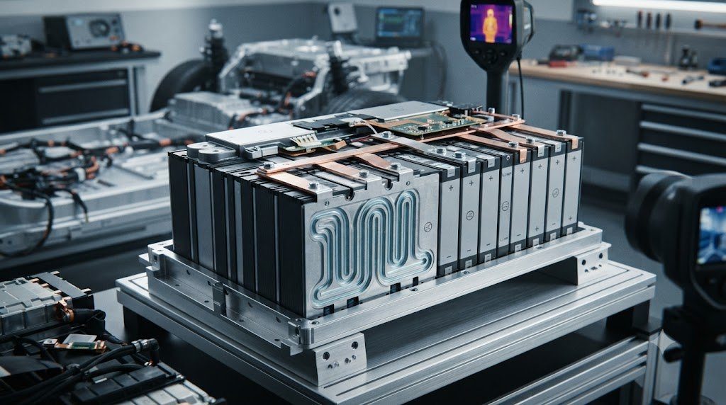
| Thermal Joule Heating | Pack Level (Hundreds of cells) | Internal resistance heating (P = I²R) | Direct-immersion dielectric fluid, dual-sided cold plates |
| Lithium Plating Boundary | Interfacial (< 1 nm surface) | Anode potential relative to 0.0V vs. Li/Li⁺ | Closed-loop 3-electrode BMS, adaptive multi-step CC |
3. Thermal Dynamics: Extreme Joule Heating (I²R) and Heat Generation Rates
Electrical power dissipation scales with the square of the charging current ($P_{loss} = I^2 \cdot R$). Comparing standard 1C charging to 4C extreme fast charging demonstrates the brutal thermal reality:
Quadrupling the charging current (from 1C to 4C) increases instantaneous heat generation by a staggering sixteen-fold ($16 imes$)! For a 100 kWh battery pack being charged at 400 kW, internal ohmic and entropic heat generation can exceed 25 to 40 kilowatts of continuous thermal power. If this massive heat flux is not evacuated instantly, cell core temperatures can surpass 60°C within minutes, triggering rapid SEI breakdown, gas generation, and thermal runaway.
4. Electrode Architecture Engineering: Low-Tortuosity Vertical Micro-Channels
To bypass liquid diffusion bottlenecks in thick commercial electrodes, materials scientists developed low-tortuosity structured electrodes:
- Laser-Patterned Micro-Channels: High-speed industrial picosecond laser ablation drills vertical microscopic holes (20 to 30 microns diameter) directly through the calendered electrode coating. These laser-drilled vertical highways allow liquid electrolyte to bypass tortuous horizontal grain boundaries, reducing effective tortuosity from $ au = 4.0$ down to $ au < 1.5$ and slashing concentration overpotentials by 50%.
- Magnetic Flake Orientation: During wet slurry coating, natural graphite flakes are doped with trace superparamagnetic iron oxide nanoparticles. Passing the wet foil through an external magnetic field forces the graphite flakes to stand up vertically perpendicular to the current collector foil before drying, orienting lithium-ion intercalation pathways directly parallel to the current flux.
5. Electrolyte Formulations for Fast Desolvation Kinetics
During fast charging, stripping the tightly bound solvent molecules from the lithium cation (the desolvation process at the SEI boundary) accounts for over 50% of total cell charge-transfer resistance:
Traditional Ethylene Carbonate (EC) binds tenaciously to lithium cations with high solvation energies. Next-generation XFC electrolytes utilize weakly solvating fluorinated ethers and carboxylate co-solvents (such as fluoroethylene carbonate paired with methyl propionate and high concentrations of LiFSI salt). These formulations lower desolvation activation energy from ~65 kJ/mol down to below 35 kJ/mol, enabling rapid lithium charge transfer at current densities exceeding 10 mA/cm² without triggering lithium plating.
6. Real-Time Lithium Plating Detection: Three-Electrode Cells and dV/dt Analysis
Preventing lithium plating during extreme fast charging requires the BMS to know exactly when the anode potential approaches the dangerous zero-volt threshold:
- Three-Electrode Reference Cells: Advanced research and development packs incorporate microscopic metallic lithium or lithium-alloy reference electrodes embedded inside the cell separator. This enables direct, independent measurement of the negative electrode potential ($E_{anode}$ vs. Li/Li⁺), allowing charging algorithms to dynamically throttle current to keep anode potential clamped precisely at +20 mV, completely preventing plating.
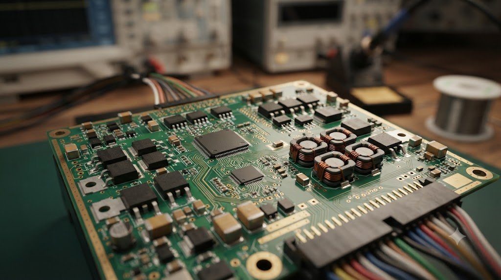
- Voltage Relaxation Plateau Analysis ($dV/dt$): When a cell completes a fast-charge pulse and current stops, plated metallic lithium begins stripping back and chemically intercalating into the underlying graphite. This chemical stripping produces a distinct, measurable voltage relaxation plateau in the open-circuit voltage curve. Machine-learning algorithms in modern automotive BMS analyze voltage relaxation derivatives in real time to instantly detect microscopic plating onset and adapt future charging profiles.
7. The 800V vs. 400V High-Voltage Architecture Revolution
To deliver 350 kW of charging power without requiring excessively thick, heavy copper cables that consumers cannot lift, the automotive industry transitioned from 400V to 800V architectures (pioneered by Porsche, Hyundai, and Audi):
- Halving Current for Identical Power: Delivering 350 kW at 400V requires an immense current of 875 Amperes, generating enormous resistive heat in cables, connectors, and internal busbars. Doubling pack nominal voltage to 800V cuts required charging current in half to ~437 Amperes ($P = V imes I$).
- Reducing Cable Mass and Heat Losses: Because resistive Joule heating scales quadratically with current ($I^2R$), halving the current slashes heat generation in charging cables and internal pack wiring by a factor of four ($75\%$ reduction). This enables lighter vehicle wiring harnesses, smaller liquid-cooled cable diameters, and higher sustained peak charging speeds.
8. Pre-Heating and Pre-Conditioning Algorithms for XFC
Counterintuitively, the secret to safe extreme fast charging is deliberately heating the battery before plugging in:
When a driver selects a DC fast charging station on an EV navigation system, the vehicle automatically initiates battery pre-conditioning. Active heat pumps and coolant heaters warm the battery pack to an optimal thermal sweet spot between 30°C and 35°C. Elevated temperature multiplies solid-state lithium diffusivity and reduces electrolyte viscosity, slashing charge-transfer resistance by over 60%. When the vehicle plugs into a 350 kW charger, the warm cells accept astronomical currents without driving anode potentials negative, safely averting lithium plating.
9. Extreme Fast Charging Degradation Trade-offs and 10-Year Warranties
While XFC provides internal combustion fueling convenience, routine unmanaged fast charging accelerates battery aging:
Extensive fleet studies show that vehicles charged exclusively on 350 kW DC fast chargers exhibit 10% to 25% faster capacity degradation over five years compared to vehicles charged slowly overnight on AC Level 2 chargers. Degradation manifests primarily as active lithium inventory loss (LLI) from continuous SEI thermal cracking and minor micro-plating. To honor 8-year / 100,000-mile warranties, automotive manufacturers program adaptive charging algorithms that limit peak 350 kW speeds to the 10% to 60% SOC window, tapering current aggressively beyond 70% SOC.
10. High-Power Charging Infrastructure and Liquid-Cooled Dispenser Cables
Delivering 350 kW to 500 kW of continuous DC electrical power from the grid into an electric vehicle requires overcoming severe electrical engineering constraints at the physical dispenser cable:
A standard uncooled copper electrical conductor rated to carry 500 Amperes continuously would require a copper cross-sectional area exceeding 150 mm², resulting in a stiff, heavy charging cable weighing over 25 kilograms that ordinary motorists would find impossible to maneuver. To resolve this, modern ultra-fast charging dispensers deploy liquid-cooled charging cables and connectors:
- Internal Coolant Circulation: A dedicated closed-loop cooling system pumps synthetic dielectric fluid or water-glycol coolant directly through coaxial internal channels surrounding the flexible copper conductors right up to the CCS or NACS connector pins.
- Thermal Pin Clamping: Active liquid cooling dissipates up to 3 to 5 kW of contact heat directly at the physical terminal pins, preventing connector handle temperatures from exceeding safe ergonomic limits (strictly capped at 50°C by UL 2202 and IEC 62196 standards) while slashing cable diameter in half and reducing cable weight by over 60%.
- Grid-Side Buffer Energy Storage: Installing multiple 350 kW chargers at a highway rest stop creates massive localized grid demand spikes exceeding 2 to 4 megawatts. To avoid crushing local distribution transformers or incurring ruinous utility demand charges, next-generation charging stations integrate 500 kWh to 2 MWh stationary lithium battery buffers that trickle-charge from the grid and discharge rapidly into vehicles during peak charging sessions.
11. Frequently Asked Questions Regarding Extreme Fast Charging (XFC)
What qualifies as Extreme Fast Charging (XFC)?
The U.S. Department of Energy defines XFC as replenishing at least 200 miles of driving range in under 10 to 15 minutes, requiring charging rates of 4C to 6C (350 kW to 500+ kW).
What is metallic lithium plating and why does fast charging cause it?
When high charging currents push the negative electrode potential below 0.0V vs. Li/Li+, lithium ions cannot intercalate fast enough and instead deposit as dangerous metallic dendrites on the particle surface.
Why do EV batteries charge slower from 80% to 100% SOC?
Above 80% SOC, graphite particles are nearly saturated with lithium; forcing high currents would cause severe lithium plating and overheating, requiring current to taper downward.
How does 800V architecture benefit fast charging compared to 400V?
800V delivers the same charging power with half the electrical current, reducing I²R heat losses by 75% and enabling lighter cables and faster sustained charging.
Why is battery pre-conditioning important before fast charging?
Warming the battery to 30°C–35°C boosts lithium diffusion kinetics and cuts internal resistance, allowing the cell to absorb high charging currents safely without lithium plating.
What causes the massive heat generation during extreme fast charging?
Joule heating scales with the square of the current (I²R); quadrupling charging current produces sixteen times more heat, generating up to 30 kW of thermal power in the pack.
What are low-tortuosity electrodes?
Electrodes with laser-drilled vertical micro-channels or vertically aligned particles that allow liquid electrolyte to reach deep active material without tortuous resistance.
How can a BMS detect lithium plating in real time?
By analyzing the open-circuit voltage relaxation plateau after charging pulses, or by measuring anode potentials directly using embedded reference electrodes.
Does frequent DC fast charging damage the battery?
Routine exclusive fast charging can accelerate capacity loss by 10% to 20% over five years due to mechanical particle micro-cracking and thermal SEI degradation.
What is desolvation resistance in fast charging?
The energy required to strip solvent molecules from the lithium ion before it can enter the electrode; this process accounts for over half of total charge-transfer resistance.
Can solid-state batteries solve the fast charging challenge?
Solid-state batteries with ceramic electrolytes eliminate flammable liquids, but high interfacial contact resistance between solid layers currently limits room-temperature fast-charging rates.
What is the role of cooled charging cables?
Liquid-cooled charging cables circulate coolant around the copper conductors, allowing thin, flexible cables to carry up to 500 Amperes continuously without overheating.