Charging a rechargeable lithium-ion battery is an intricate balance between electrochemical thermodynamics, mass transport kinetics, and solid-state diffusion limits. The universally adopted foundation of lithium battery charging is the Constant Current / Constant Voltage (CC/CV) protocol. Managing the transition between these two distinct electrochemical regimes, calibrating end-of-charge saturation current cut-offs (C/20 to C/50), preventing parasitic electrolyte decomposition, and designing adaptive multistage charging profiles dictate the operational boundary between rapid replenishment and premature cell degradation.
The Core Principle of CC/CV Charging
Directly connecting a lithium battery to an unregulated voltage source causes massive inrush currents that trigger catastrophic overheating and internal short circuits. Conversely, applying a constant high current continuously without voltage clamping forces electrode potentials to skyrocket, causing catastrophic electrolyte oxidation and metallic lithium dendrite plating. CC/CV resolves this by separating charging into a bulk constant-current phase followed by a saturation constant-voltage tapering phase.
1. Phase 1: Constant Current (CC) Bulk Charging Kinetics
During the initial Constant Current (CC) phase, the battery charger functions as a regulated current source, delivering a fixed electrical current (typically rated between 0.5C and 1.5C for standard consumer and EV cells):
- Rapid State of Charge (SOC) Accumulation: The CC phase is responsible for replenishing approximately 70% to 80% of total cell capacity in the shortest possible timeframe. During this regime, terminal voltage rises monotonically from the empty cut-off threshold (typically 2.8V to 3.0V) toward the maximum design voltage limit (typically 4.20V for NMC/LCO, 3.65V for LFP).
- Overpotential Components: The cell terminal voltage ($V_{term}$) measured at external terminals is always higher than the true thermodynamic open-circuit voltage ($OCV$) due to three distinct overpotentials:
V_{term} = OCV(SOC) + I \cdot R_{ohmic} + \eta_{charge-transfer} + \eta_{diffusion}
Ohmic overpotential is instantaneous, while charge-transfer and solid-state concentration diffusion overpotentials grow progressively as lithium ions populate the graphite host matrix.
- Transition Trigger: As soon as terminal voltage reaches the pre-set upper cut-off voltage ($V_{max}$), the charger instantaneously switches from current regulation to voltage regulation, terminating the CC phase.
2. Phase 2: Constant Voltage (CV) Saturation and Current Tapering
Upon hitting the upper voltage threshold, the battery is far from 100% full. In fact, if charging were terminated immediately at the end of the CC phase, the cell would instantly rebound downward to an open-circuit voltage corresponding to only 70% to 80% true state of charge. To reach full chemical saturation, the cell enters the Constant Voltage (CV) phase:
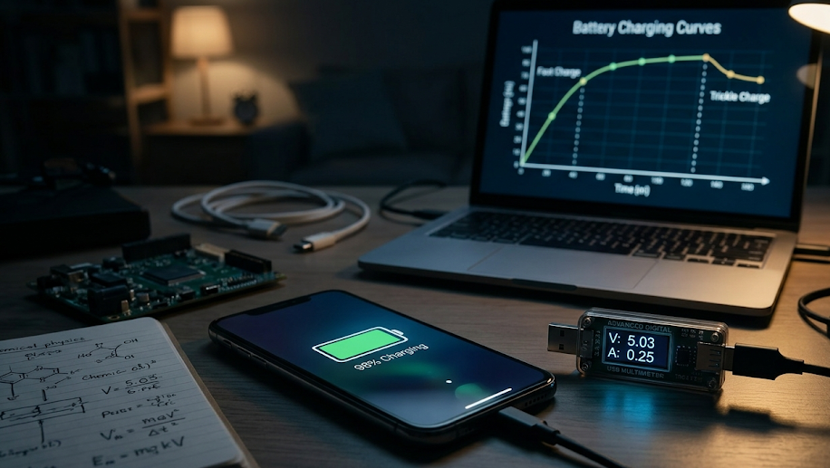
In the CV stage, the charger clamps terminal voltage rigidly at the target setpoint (e.g., exactly 4.200V ± 0.5%). As lithium ions diffuse deeper into the core of active graphite particles, the internal concentration gradient flattens. Because the driving overpotential narrows, the charging current naturally tapers downward in an exponential decay curve governed by Fick’s laws of solid-state diffusion.
| Charging Parameter / Metric | Constant Current (CC) Phase | Constant Voltage (CV) Phase | Float / Maintenance Mode |
|---|---|---|---|
| Primary Controller Role | Regulated Current Source (Amps clamped) | Regulated Voltage Source (Volts clamped) | Low-Voltage Clamping (Trickle offset) |
| Terminal Voltage Behavior | Rises rapidly from 3.0V to 4.20V | Rigidly clamped at 4.200V (± 10 mV) | Held at conservative float level (~4.05V) |
| Charging Current Behavior | Constant (0.5C to 2.0C) | Exponential decay tapering toward 0 | Minimal current offsetting self-discharge |
| Capacity Replenished | ~70% to 80% of total Ah | ~20% to 30% of total Ah (Saturation) | 0% (Offsets internal parasitic leakage) |
| Dominant Stress Factor | Ohmic Joule heating (I²R) | High-voltage oxidative electrolyte stress | Accelerated calendar aging if voltage high |
| Typical Duration | 30 to 60 minutes | 30 to 90 minutes | Continuous (Standby / UPS systems) |
3. End-of-Charge Cut-off Criteria: The C/20 to C/50 Taper Threshold
A critical engineering parameter in CC/CV algorithm design is determining exactly when to stop charging. Because the CV current decays asymptotically, it theoretically approaches zero infinitely slowly. Charging must be terminated when current drops below a designated saturation cut-off threshold:
- Standard Cut-off Current ($I_{cut} = C/20$ to $C/50$): For a 100 Ah battery pack, charging is officially complete when tapering current drops below 5.0 Amps (C/20) or 2.0 Amps (C/50). Cutting off at C/20 captures ~98% of total theoretical capacity while cutting CV time by 40 minutes.
- The Hazard of Continuous Trickle Charging: Unlike lead-acid or nickel-cadmium batteries, lithium-ion chemistry cannot absorb continuous trickle charge. If a charger maintains 4.20V indefinitely, the continuous micro-current forces transition metals to catalyze electrolyte solvent oxidation, generating acidic byproducts and degrading the positive electrode lattice. Lithium chargers must feature absolute positive cut-off switches.
- Backup Safety Termination Timers: To protect against malfunctioning cells with internal micro-shorts that prevent current from tapering down to the cut-off threshold, industrial Battery Management Systems (BMS) enforce maximum CV timers (typically 60 to 90 minutes), cutting charging power regardless of measured current.
4. Pre-Charge (Trickle) Regimes for Deeply Discharged Cells
When a lithium-ion cell is over-discharged below its critical stability threshold—typically below 2.0V to 2.5V—applying full CC bulk current (1C) is extremely hazardous:
At potentials below 1.5V vs. Li/Li⁺, the copper current collector foil on the anode undergoes anodic dissolution, dissolving metallic copper into $Cu^{2+}$ ions that disperse into the liquid electrolyte. If high current is applied immediately, dissolved copper ions reduce into microscopic metallic copper dendrites that permanently puncture the separator, causing catastrophic dead shorts. To safely recover over-discharged cells, chargers enforce a Pre-Charge Phase (0.05C to 0.1C) until cell voltage climbs back above 3.0V, ensuring current collectors and SEI layers stabilize before high current injection.
5. Multistage Constant Current (MCC) and Pulse Charging Innovations
While CC/CV is reliable, the prolonged duration of the CV phase represents a severe bottleneck for electric vehicle fast charging. To slash charging times without accelerating degradation, battery engineers developed Multistage Constant Current (MCC) protocols:
- Step-Down Current Cascades: Instead of a single CC current followed by an analog CV taper, MCC applies a discrete ladder of decreasing current steps: for example, 3C from 0% to 30% SOC, 2C from 30% to 55% SOC, 1C from 55% to 75% SOC, and 0.5C from 75% to 90% SOC. By stepping current downward as internal solid-state diffusion resistance climbs, the cell voltage is held safely below the lithium plating boundary without spending excessive time in the slow CV tail.
- Pulse Charging and Depolarization Pauses: Pulse charging alternates short bursts of high-rate charge current with brief rest periods (or even microscopic reverse-discharge depolarization pulses). These rest intervals allow localized lithium ion concentration gradients at the anode surface to relax and diffuse into graphite bulk, suppressing concentration polarization and mitigating dendrite nucleation.
6. Temperature-Compensated Charging Windows and Cold Inhabitation
Lithium battery charging protocols must dynamically adapt to ambient and internal core temperatures via strict JEITA charging guidelines (Japan Electronics and Information Technology Industries Association):
- Sub-Zero Charging Prohibition (< 0°C): Below freezing, lithium ion diffusion kinetics in graphite drop by over an order of magnitude. If charging current exceeds C/20 at 0°C, intercalating lithium ions cannot enter graphite interlayers and instead deposit as metallic lithium dendrites directly on the graphite surface, sparking severe fire hazards. Advanced BMS systems completely disable charging below 0°C until internal battery pack heaters warm cells above +5°C.
- High-Temperature Voltage De-rating (> 45°C): At temperatures above 45°C, high cut-off voltages accelerate cathode transition metal dissolution and electrolyte transesterification. The BMS dynamically lowers the maximum CV setpoint from 4.20V down to 4.05V or 4.10V to prevent runaway parasitic side reactions.
7. Coulombic Efficiency and Energy Efficiency Thermodynamics
Evaluating charging protocol quality requires quantifying two fundamental thermodynamic efficiencies:
- Coulombic Efficiency (Ampere-Hour Efficiency): Defined as the ratio of discharge capacity to charge capacity ($\eta_C = Q_{discharge} / Q_{charge} imes 100\%$). In high-quality lithium cells operating under optimal CC/CV control, Coulombic efficiency exceeds 99.9% to 99.95%. Any fraction below 100% represents parasitic electron-consuming side reactions, such as continuous SEI growth or electrolyte oxidation.
- Energy Efficiency (Watt-Hour Efficiency): Defined as the ratio of electrical energy released during discharge to electrical energy consumed during charging ($\eta_E = E_{discharge} / E_{charge} imes 100\%$). Because the charging voltage curve sits above the discharge voltage curve due to internal overpotentials ($I \cdot R$ hysteresis losses), energy efficiency typically ranges from 92% to 96%. Fast charging at high C-rates increases overpotential separation, degrading round-trip energy efficiency and dissipating lost energy as waste heat.
8. Charger Hardware Topologies: Buck, Boost, and LLC Resonant Converters
Executing precise CC/CV control requires high-efficiency power electronics conversion architectures:
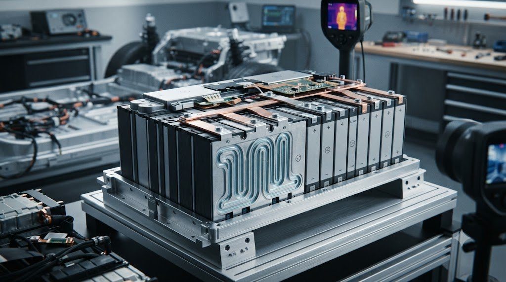
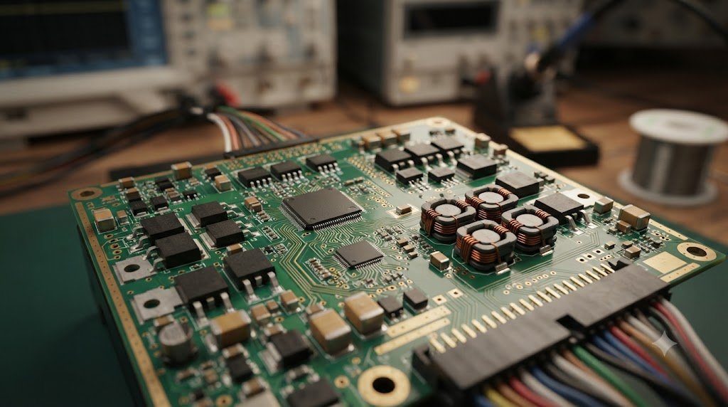
Modern on-board chargers (OBC) and grid-connected DC fast chargers convert alternating current (AC) to direct current (DC) using isolated LLC Resonant Converters paired with Silicon Carbide (SiC) and Gallium Nitride (GaN) wide-bandgap semiconductors. These converters operate at switching frequencies exceeding 100 kHz with Zero-Voltage Switching (ZVS), achieving energy conversion efficiencies exceeding 96% to 98%. Digital signal processors (DSP) execute closed-loop proportional-integral-derivative (PID) control loops every microsecond, guaranteeing that transition from constant current to constant voltage occurs without terminal voltage overshoot spikes that could damage delicate SEI layers.
9. Degradation Trade-offs: Voltage De-rating for 10-Year Calendar Longevity
In consumer electronics and electric vehicles, battery lifespan can be multiplied dramatically by sacrificing a negligible fraction of peak driving range:
Operating a cell to a full 4.20V cut-off stresses the layered oxide cathode and accelerates electrolyte oxidation. By de-rating the CV voltage setpoint by just 100 millivolts (charging to 4.10V instead of 4.20V), available capacity drops by approximately 10% to 15%, but cell cycle life doubles from 800 cycles to over 2,000 cycles! This strategy is widely deployed in commercial grid storage and aerospace satellites, where 15-to-20-year operational longevity takes absolute precedence over maximum single-cycle energy density.
10. Frequently Asked Questions Regarding Battery Charging Protocols
What does CC/CV stand for in battery charging?
CC/CV stands for Constant Current / Constant Voltage, a two-phase protocol where bulk current is supplied first, followed by a clamped voltage phase to saturate capacity safely.
Why can’t you charge a lithium battery with constant current all the way to 100%?
Charging with high current past the cut-off voltage would cause terminal voltage to spike dangerously, decomposing liquid electrolyte and plating hazardous metallic lithium on the anode.
What happens during the Constant Voltage (CV) phase?
The voltage is clamped at maximum (e.g., 4.20V), and current gradually tapers down as lithium ions diffuse into the graphite particles until the battery reaches full chemical saturation.
What is the typical end-of-charge cut-off current threshold?
Charging typically stops when the tapering current in the CV phase drops below C/20 to C/50 (for example, below 2A on a 100Ah battery pack).
Why should lithium-ion batteries never be trickle charged continuously?
Unlike lead-acid, lithium batteries cannot absorb continuous overcharge current; floating at high voltage continuously accelerates electrolyte breakdown, gas generation, and cell swelling.
Why is charging prohibited below freezing (0°C)?
Below 0°C, lithium ion diffusion slows down drastically; forced charging causes lithium ions to plate as sharp metallic dendrites on the anode surface, creating short-circuit fire hazards.
What is Multistage Constant Current (MCC) charging?
MCC uses a stepped ladder of decreasing constant current stages to charge faster than CC/CV while preventing cell voltage from exceeding safety thresholds.
What is a Pre-Charge phase and when is it required?
Pre-charge applies a very low current (0.05C to 0.1C) to deeply over-discharged cells (below 2.5V) to restore safe voltage levels without dissolving copper current collectors.
How does de-rating charging voltage from 4.20V to 4.10V affect battery lifespan?
Lowering the peak voltage by 100 mV sacrifices about 10-15% of single-charge capacity but doubles or triples total cycle lifespan by reducing chemical oxidation stress.
What is Coulombic efficiency during charging?
Coulombic efficiency is the ratio of discharge capacity to charge capacity; in high-quality lithium cells, it exceeds 99.9%, indicating minimal lost energy from parasitic reactions.
Why does the CV phase take so long compared to the CC phase?
Solid-state diffusion of lithium ions into the core of active material particles is slow, causing current to decay exponentially as the concentration gradient flattens.
What are the JEITA charging guidelines?
JEITA guidelines are industry standards that automatically de-rate charging current and maximum cut-off voltage at extreme low and high temperatures to preserve safety and longevity.