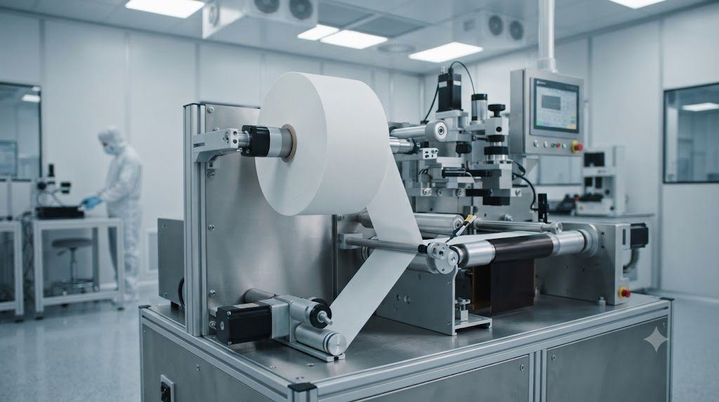
The negative electrode (anode) of a lithium-ion battery dictates cell charging speed, initial Coulombic efficiency, volumetric expansion behavior, and calendar life. While synthetic and natural graphite have reigned as the undisputed workhorse anode materials for over three decades, the relentless pursuit of electric vehicle driving range and fast-charging parity with internal combustion fueling has ignited a materials revolution: Silicon-Carbon (Si-C) composites and advanced pre-lithiated alloy architectures. Balancing graphite’s dimensional stability with silicon’s tenfold higher theoretical capacity represents the definitive battleground of contemporary anode engineering.
The Gravimetric Capacity Divide
Standard graphite intercalates one lithium atom for every six carbon atoms (LiC6), yielding a theoretical specific capacity of exactly 372 mAh/g. In contrast, elemental silicon alloys with lithium to form Li15Si4, delivering an astronomical theoretical capacity of 3,579 mAh/g. However, silicon undergoes a brutal 300% volumetric expansion during lithiation, compared to graphite’s modest 10%.
1. Graphite Anodes: Natural vs. Synthetic Graphitization Dynamics
Graphite is an allotrope of carbon consisting of planar graphene sheets bonded by strong sp² covalent bonds, with adjacent sheets held together by weak van der Waals forces separated by an interlayer spacing of d₀₀₂ = 0.3354 nanometers. During battery charging, lithium ions stage sequentially between graphene layers ($C o LiC_{18} o LiC_{12} o LiC_6$).
Natural Flake Graphite (Spheronized and Pitch-Coated)
Mined directly from metamorphic geological deposits (predominantly in China, Mozambique, and Brazil), natural graphite occurs as flat, jagged flakes. To make it suitable for battery slurries, raw flakes undergo mechanical milling into spherical pebbles (spheronization). Spherical particles pack with higher tap density (> 1.0 g/cm³) and minimize anisotropic tortuosity. Because bare natural graphite flakes suffer from edge-plane solvent co-intercalation (where propylene carbonate molecules wedge into graphite sheets and exfoliate the layers apart), spheronized particles are encapsulated in a 5-to-10-nanometer layer of amorphous pyrolytic coal-tar pitch.
Synthetic (Artificial) Graphite
Synthetic graphite is manufactured from needle coke (a petroleum refining byproduct) or coal pitch. The green precursor is baked in Acheson graphitization furnaces at scorching temperatures exceeding 2,800°C to 3,000°C for weeks. This intense thermal treatment vaporizes volatile sulfur and nitrogen impurities, converting disordered carbon into pristine, highly crystalline graphite. Synthetic graphite features isotropic grain alignment, superior mechanical fatigue resistance, and longer calendar life ($> 10$ years), making it the preferred anode choice for high-mileage electric vehicles and grid energy storage.
| Property / Parameter | Natural Flake Graphite | Synthetic (Artificial) Graphite | Silicon-Carbon Composite (10% Si) |
|---|---|---|---|
| Theoretical Capacity | 372 mAh/g | 372 mAh/g | ~650 – 750 mAh/g |
| Practical Reversible Capacity | 350 – 360 mAh/g | 340 – 355 mAh/g | 550 – 650 mAh/g |
| Volumetric Expansion | ~9% to 12% | ~8% to 10% | 25% to 45% (Locally > 200%) |
| First-Cycle Efficiency (ICE) | 90% – 93% | 92% – 95% | 82% – 88% (Without pre-lithiation) |
| Cost ($/kg) | Low ($4 – $7 / kg) | Moderate to High ($8 – $15 / kg) | High ($25 – $50 / kg) |
| Carbon Footprint | Low (~2 – 5 kg CO2/kg) | Very High (~15 – 25 kg CO2/kg) | Moderate (~10 – 18 kg CO2/kg) |
| Fast-Charge Capability | Moderate (Risk of plating) | Good (Isotropic crystal grains) | Exceptional (Fast alloy kinetics) |
2. The Silicon Frontier: Alloying Mechanics and 300% Volumetric Expansion
Silicon does not store lithium via gentle intercalation between atomic sheets; it stores lithium via an electrochemical alloying reaction. As lithium ions enter crystalline silicon (c-Si), the material undergoes progressive amorphization, transitioning through amorphous phases (a-Li_xSi) before abruptly crystallizing into metastable $Li_{15}Si_4$ at deep potentials below 50 millivolts.
Accommodating 3.75 lithium atoms for every single silicon atom forces the crystal lattice to expand by over 300% in volume. When a bare micro-sized silicon particle expands and contracts during cycling, three catastrophic failure modes occur simultaneously:
- Mechanical Particle Pulverization: Immense internal hoop stresses exceed the fracture toughness of silicon, shattering primary particles into disconnected nanoscale debris.
- Electrode Delamination: The expanding electrode expands outward, severing electrical contact with the copper current collector foil and conductive carbon additive networks.
- Continuous SEI Destruction and Reformation: The Solid Electrolyte Interphase layer formed on silicon is brittle. As the particle breathes, the SEI cracks open, exposing bare lithiated silicon to liquid solvent. Fresh SEI forms to heal the rupture, continuously consuming cyclable lithium and drying out liquid electrolyte until the cell dies within dozens of cycles.
3. Nanoscale Silicon Engineering: Carbon Nanotubes, Yolk-Shell, and SiO_x
To harness silicon’s astronomical capacity without triggering mechanical self-destruction, advanced nanomaterials engineers designed sophisticated architectural hosts:
Silicon Oxide (SiO_x) Composites
Disproportionated silicon monoxide ($SiO_x$, where $x pprox 1$) consists of ultrafine, amorphous silicon nanoclusters (1 to 3 nm) uniformly dispersed within a rigid, amorphous silicon dioxide ($SiO_2$) ceramic matrix. During the initial formation charge, the $SiO_2$ matrix reacts irreversibly with lithium to generate in-situ lithium silicate ($Li_4SiO_4$) and lithium oxide ($Li_2O$). While this consumes initial lithium capacity, the formed silicate matrix acts as a mechanically rigid elastic cushion that buffers the 300% volume expansion of the embedded silicon nanoclusters, enabling thousands of stable cycles.
Yolk-Shell and Porous Carbon Scaffolds
Pioneered by Professor Yi Cui at Stanford University, yolk-shell architectures enclose individual silicon nanoparticles inside hollow, conductive carbon shells with engineered internal void space. When the silicon core “yolk” expands during lithiation, it expands freely into the hollow cavity without deforming or cracking the outer carbon “shell”. Because the outer shell remains dimensionally static, a stable, un-cracked SEI layer forms on the carbon exterior, halting continuous electrolyte decomposition.
4. Polymeric Binders for High-Strain Anodes: PAA, CMC, and SBR
In standard graphite electrodes, the binder of choice is polyvinylidene fluoride (PVDF) dissolved in toxic N-methyl-2-pyrrolidone (NMP) solvent, or aqueous Carboxymethyl Cellulose (CMC) paired with Styrene-Butadiene Rubber (SBR). However, weak van der Waals bonding between PVDF and silicon particles is utterly incapable of surviving 300% volume expansion.
Silicon-dominant anodes require specialized high-elasticity aqueous polymeric binders:
- Polyacrylic Acid (PAA): Possesses a high density of carboxylic acid ($-COOH$) groups that form strong, covalent-like hydrogen bonds with native silanol ($-Si-OH$) groups on silicon surfaces, providing self-healing mechanical elasticity under repetitive volume swings.
- Sodium Alginate: Extracted from natural brown seaweed, alginate contains uniformly structured carboxylic groups that form coordinated crosslinked networks with divalent cations ($Ca^{2+}$), delivering superior tensile strength.
5. Pre-Lithiation Technologies: Restoring First-Cycle Lost Lithium
Because silicon anodes suffer from 15% to 30% first-cycle irreversible capacity loss (ICL) during initial SEI formation, cell manufacturers utilize pre-lithiation to inject sacrificial lithium into the anode before cell cycling begins:
- Stabilized Lithium Metal Powder (SLMP): Microscopic droplets of metallic lithium coated with a protective sub-micron lithium carbonate ($Li_2CO_3$) or wax shell. SLMP is sprinkled onto dry anode laminates and calendered; the mechanical pressure fractures the protective shell, allowing metallic lithium to diffuse into graphite and silicon particles.
- Electrochemical Pre-Lithiation Baths: Anode rolls are submerged in electrolytic baths opposite a sacrificial lithium metal foil electrode, applying a continuous electrical current to pre-form a pristine SEI layer before assembly into the final cell housing.
6. Carbon Nanotubes (CNTs) as Anode Conductive Highways
Traditional carbon black (Super P) conductive additives consist of point-contact spherical nanoparticles. When silicon particles shrink during discharge, point contacts break, electrically isolating the silicon grains. Advanced silicon-carbon electrodes incorporate Single-Walled and Multi-Walled Carbon Nanotubes (SWCNTs / MWCNTs):
Carbon nanotubes feature astronomical length-to-diameter aspect ratios exceeding 1,000:1 and tensile strengths sixty times higher than steel. SWCNTs form a flexible, three-dimensional spiderweb that physically wraps around expanding silicon and graphite particles, maintaining continuous electrical percolation networks even after hundreds of severe expansion cycles.
7. Anode Calendering and Electrode Tortuosity Physics
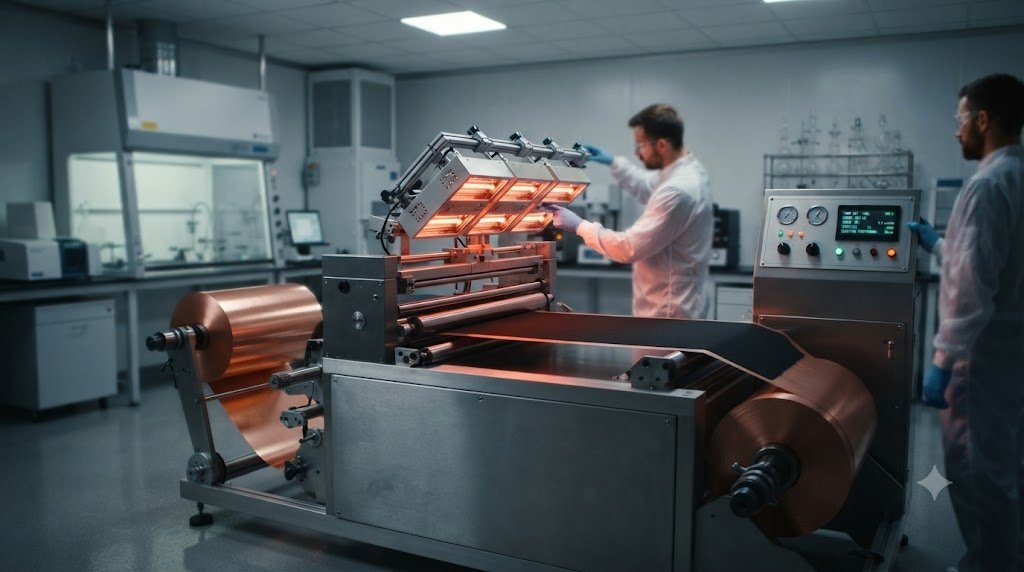
Following slurry coating and drying, anode laminates pass through precision heated roll presses in a process called calendering. Calendering compresses loose coated powder to achieve an optimal electrode compaction density (typically 1.55 to 1.70 g/cm³ for graphite):
- The Volumetric Capacity Trade-off: High compaction increases volumetric capacity and reduces electron contact resistance between graphite flakes. However, over-calendering (> 1.75 g/cm³) flattens and aligns graphite flakes horizontally parallel to the current collector, creating immense anisotropic pore tortuosity (tau > 4).
- Fast-Charging Bottlenecks: When pores become overly tortuous, liquid lithium ions cannot diffuse down through the thickness of the electrode during high-rate charging. Lithium ions pile up at the separator-anode interface, causing premature concentration polarization that triggers destructive metallic lithium dendrite plating. Modern fast-charging anodes utilize laser patterning or magnetic flake alignment to create vertical low-tortuosity diffusion highways.
8. The Ultimate Frontier: Pure Metallic Lithium Anodes (Li-Metal)
The absolute theoretical zenith of negative electrode engineering is eliminating the host graphite matrix altogether and utilizing pure metallic lithium foil (3,860 mAh/g capacity, density 0.534 g/cm³):
Pure lithium metal anodes allow pack-level energy densities to leap beyond 450 to 500 Wh/kg. However, in liquid electrolytes, stripping and plating metallic lithium during cycling creates non-uniform electric field “hotspots” that sprout mossy, dendritic lithium needles. These dendrites pierce conventional separators, causing explosive internal shorts. Furthermore, repeated plating forms electronically isolated fragments of un-contacted metal termed “dead lithium”, causing rapid Coulombic efficiency collapse. Stabilizing metallic lithium anodes requires solid-state ceramic separators (LLZO), high-pressure mechanical spring clamping (1 to 5 MPa), or localized high-concentration fluorinated electrolytes.
9. Industrial Anode Slurry Rheology and Aqueous Processing
Scaling high-content silicon-carbon anodes from laboratory coin cells to automotive roll-to-roll production lines requires overcoming severe slurry rheology and dispersion instabilities:
- Aqueous Hydrogen Gas Generation: Nano-silicon particles possess native surface oxide layers with reactive silanol groups ($-Si-OH$) that react with basic water in aqueous slurries ($Si + 2H_2O o SiO_2 + 2H_2$). This releases microscopic hydrogen bubbles that create pinholes and crater defects during high-speed slot-die coating. Formulators buffer slurry pH to 6.0 to 6.8 using weak organic acids to halt hydrogen bubbling.
- Zeta Potential Stabilization: High-surface-area silicon and carbon nanotubes agglomerate violently under van der Waals attractions. By regulating slurry zeta potential (zeta < -30 mV) using specialized ammonium polyacrylate dispersants, particles electrostatically repel each other, ensuring homogeneous dispersion and uniform electronic percolation across kilometer-long copper foil rolls.
10. Frequently Asked Questions Regarding Anode Materials
What is the theoretical capacity of a graphite anode?
Graphite has a theoretical capacity of 372 mAh/g, based on its maximum lithium intercalation stoichiometry of LiC6.
Why is silicon added to graphite anodes in modern batteries?
Elemental silicon has nearly ten times the capacity of graphite (3,579 mAh/g). Adding just 5% to 15% silicon boosts total battery energy density and driving range by 10% to 20%.
What is the main problem with using pure silicon as a battery anode?
Silicon expands by over 300% when fully charged with lithium, pulverizing particles, breaking electrical connections, and destroying the protective SEI layer.
What is the difference between natural and synthetic graphite?
Natural graphite is mined from the ground and spheronized at lower cost; synthetic graphite is synthesized from petroleum coke at 3,000°C, offering longer cycle life and better fast charging.
What is Silicon Oxide (SiOx)?
SiOx consists of nanometer-sized silicon clusters embedded in an amorphous silicon oxide matrix, which cushions volume expansion and delivers thousands of stable cycles.
What is pre-lithiation?
Pre-lithiation is the process of adding sacrificial lithium to the anode before sealing the battery, offsetting the lithium consumed during initial SEI formation.
Why are carbon nanotubes (CNTs) used in silicon anodes?
CNTs form a tough, flexible 3D conductive web that maintains electrical contact with silicon particles even as they expand and contract.
What is the role of the anode current collector foil?
Copper foil serves as the negative current collector because metallic lithium does not alloy with copper at low voltages (unlike aluminum, which would corrode).
What causes lithium plating on the graphite anode?
Fast charging at high currents or charging below freezing drives the anode potential below 0V vs. Li/Li+, causing metallic lithium to deposit on the surface instead of intercalating.
What binders are used for silicon anodes?
Water-soluble binders like Polyacrylic Acid (PAA) and Sodium Alginate are used because they form strong covalent-like hydrogen bonds that hold silicon particles together.
What is ‘dead lithium’ and why is it dangerous?
Dead lithium consists of metallic lithium fragments that lose electrical contact with the electrode during uneven discharge stripping, causing irreversible capacity fade and safety hazards.
How much silicon is practically used in commercial EV batteries today?
Most commercial high-energy EV batteries use between 5% and 10% silicon oxide or silicon-carbon composite blended with synthetic graphite to optimize energy density without compromising 1,000-cycle life.